Designing an enclosure, start to finish
EnclosureAI builds a 3D-printable box around a real electronics board — pick one from the library, add the ports it needs, and export an STL. This page walks through the whole flow with screenshots of the real app.
1Open the designer
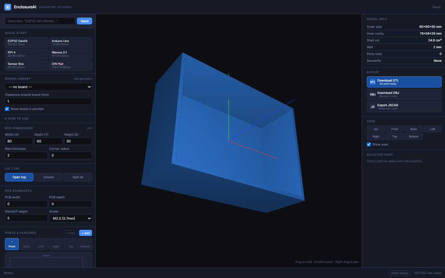
This is what you see before picking anything — a default box, a Quick start list of common board sizes, and the Board library dropdown where the real work starts.
2Pick a board
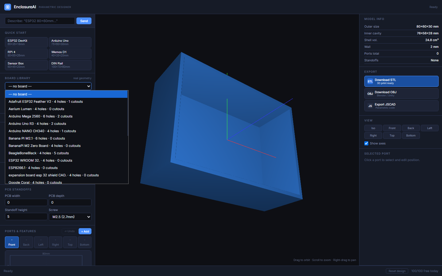
The Board library dropdown lists every board with real, verified geometry — each entry shows how many mounting holes and connector cutouts it has. Boards with real STEP/STL data behind them mean the enclosure that gets generated actually matches the physical part, not a guess.
3Your enclosure, auto-sized
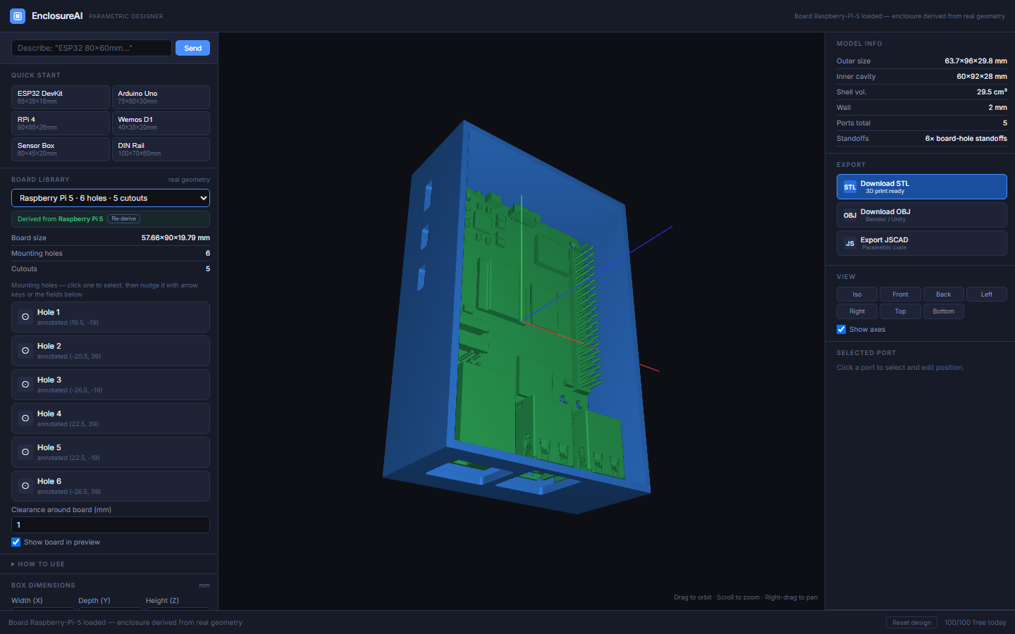
The moment you pick a board, the box resizes to fit it, standoffs appear under its real mounting holes, and any known connector cutouts are already cut into the walls. The Model info panel (top right) shows the outer size, inner cavity, and a running port/standoff count.
4Add a port or feature
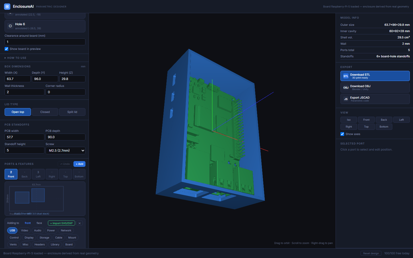
Need something the board doesn't already have — a button, a vent, an extra USB cutout? Pick which face you're adding to along the top of the Ports & features list, hit + Add, and choose from the categories: USB, Video, Audio, Power, Network, Control, Display, Storage, Cable, Mount, Vents, Misc, and pin Headers (GPIO, ICSP, camera ribbon connectors).
5Adjust a cutout's position
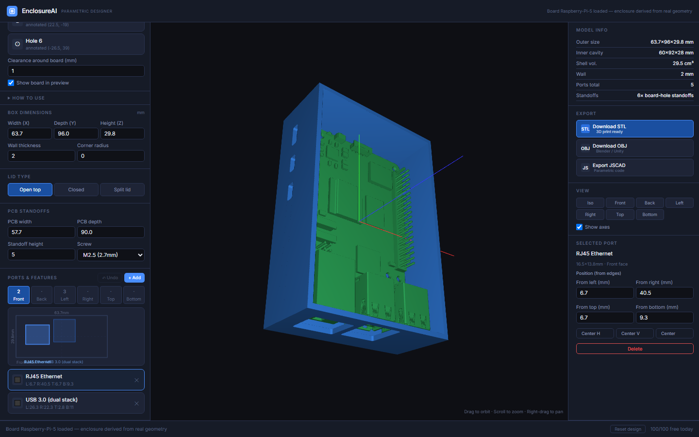
Click any row in the Ports & features list to select it — the little face diagram highlights it, and a position editor appears on the right with exact From left / right / top / bottom distances in millimetres. You can also just click a spot on the face diagram to drop it there.
6Fix a mounting hole, if one's off
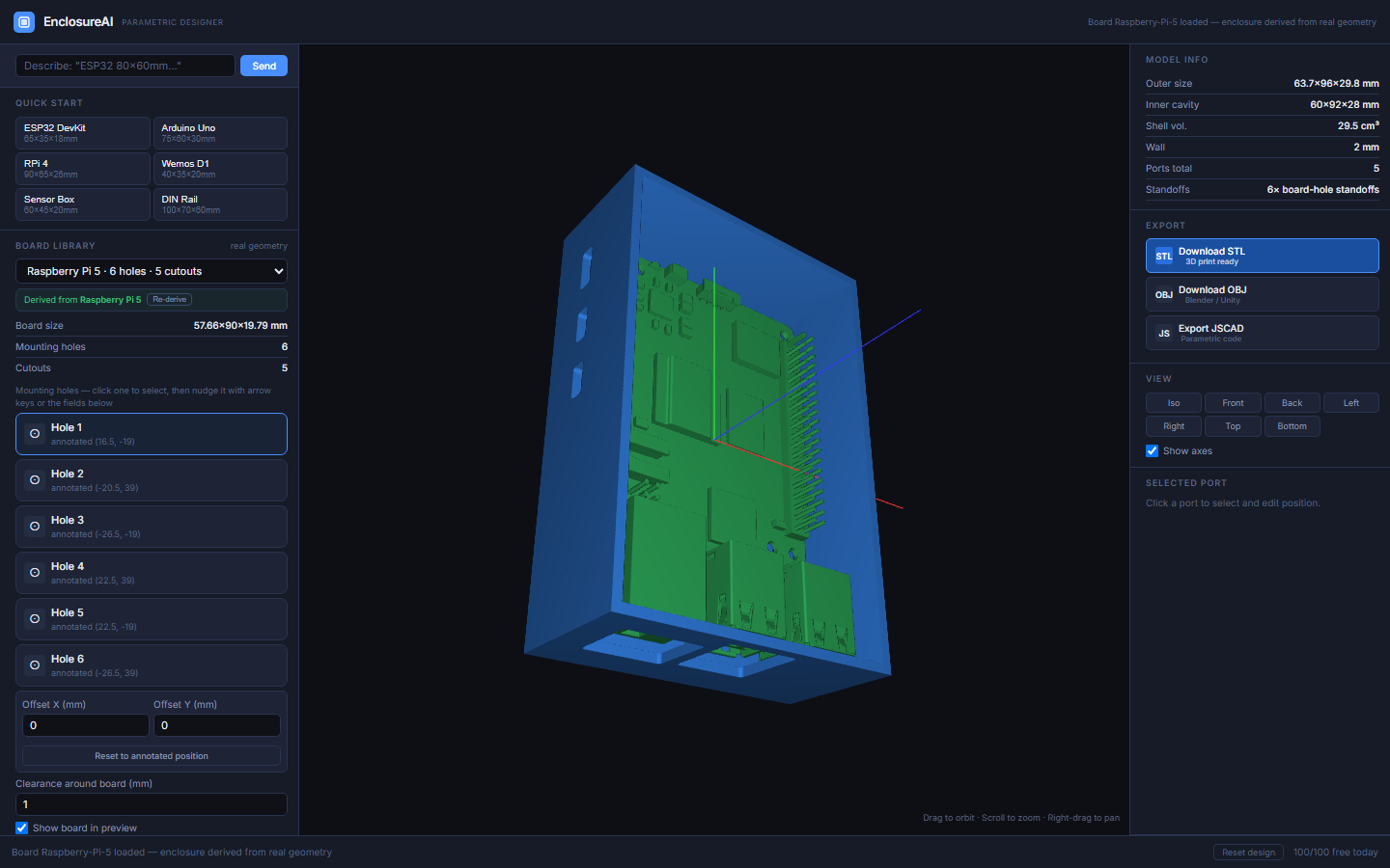
Board mounting holes come from real annotated data, but occasionally one's a little off. The Mounting holes list (under Board library) lets you select any hole and nudge just its standoff — the same arrow-key shortcut works here too. Reset to annotated position always gets you back to the real, original spot.
7Look at it from every side
The View panel (top right, visible in the screenshot above) has one button per side — Iso, Front, Back, Left, Right, Top, Bottom — for snapping the camera straight to that wall. Handy for checking a cutout lines up before you print.
8Export
Happy with the design? The Export panel (also visible above) has three options: Download STL for printing, Download OBJ for Blender/Unity, and Export JSCAD for the parametric source code, if you want to keep tweaking it programmatically.
Good to know
- My board isn't in the library
- Type dimensions manually, describe the board in the AI bar at the top, or drop its STL/STEP file into the project's board folder and annotate it once — see the project README for that workflow.
- I made a mistake — how do I undo?
- Ctrl/Cmd + Z undoes the last change to the ports list (adding, deleting, or a template/AI-fill replacing everything).
- Will I lose my work if I close the tab?
- No — the app autosaves your design as you go, including the board you picked and every port's position.